
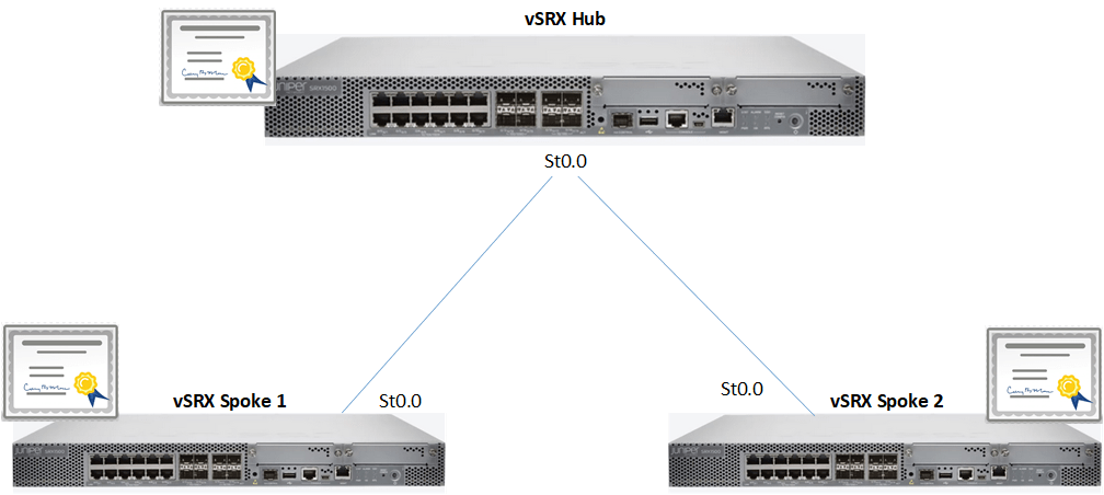
This blog discusses Juniper’s implementations of Hub and Spoke VPNs using SRX devices. The blog gives a basic understanding of what a hub and spoke VPN is, as well as sample configurations based on the topology in the image above. It should be noted that this discussion focusses on route based VPNs.
Simply put a hub and spoke VPN allows one device (the hub) to terminate VPN tunnels from multiple endpoints (spokes). Traffic between spokes can be allowed to flow through the hub without the need to create VPN tunnels between spokes. Policies can be created on the SRX to allow or deny traffic between spokes based on the organizations needs.
There are two ways to implement the hub and spoke VPN using SRX devices:
Multiple Point to Point Interfaces
Multiple Point to Point interfaces: The first way to implement the hub and spoke VPN would utilize multiple point to point secure tunnel (st0) interfaces on the hub gateway. This approach would require that each secure tunnel (st0) interface is mapped to a spoke (gateway) in the firewall’s VPN configuration. The route to remote sites would also need to point to the relevant st0 interface unless a dynamic routing protocol like OSPF is used. The drawback with this approach is that as spokes increase, the configurations and management can become tedious. The example in this blog does not use this approach.
Point-to-MultiPoint
Point-to-MultiPoint: This approach uses one (1) st0 interface for VPN connection to all spokes (gateways). The st0 interface is configured as a point-to-multipoint interface, this allows us to use the one interface for all connections.
When using this approach, the st0 interface of each device must be assigned an IP address. This IP address is used in the static / dynamic routing on the firewall. The routes no longer point to the st0 interface itself but to the IP address of the remote st0 interface. It should be noted that when using this approach a next-hop tunnel binding table is used allow Junos to bind multiple IPsec security associations to the same st0 interface. Junos uses a combination of the route table and next-hop tunnel binding table to allow routing to subnets at different spokes. Once all devices are SRX devices, this table is automatically populated.
Hub and Spoke VPN: Point-to-Multipoint Example
This example follows the topology in the opening image using three vSRX devices. Three zones were created on the SRX devices: 1) untrust zone – ge-0/0/0, 2) VPN Zone (st0) and 3) Trust Zone lo0. The loopback interface in the trust zone is used to simulate traffic from a trusted source when testing the VPN. The setup is seen in the diagram below:

The configurations shown below will reference the relevant configuration from the Hub and one (1) Spoke. The configurations assume you understand the basic setups of VPNs and as such would not provide an explanation for each line.
Interface Configuration Hub:
set interfaces ge-0/0/0 unit 0 family inet address 192.168.10.3/24
set interfaces lo0 unit 0 family inet address 10.10.3.1/24
set interfaces st0 unit 0 multipoint
set interfaces st0 unit 0 family inet address 10.25.0.3/24
Take note that the st0 interface is set to multipoint and assigned an IP address.
Interface Configuration Spoke:
set interfaces ge-0/0/0 unit 0 family inet address 192.168.10.2/24
set interfaces lo0 unit 0 family inet address 10.10.2.1/24
set interfaces st0 unit 0 family inet address 10.25.0.2/24
This st0 interface is only assigned an IP but not made a multipoint interface.
Hub IKE Configuration:
set security ike proposal ike-lab authentication-method pre-shared-keys
set security ike proposal ike-lab dh-group group2
set security ike proposal ike-lab authentication-algorithm sha1
set security ike proposal ike-lab encryption-algorithm 3des-cbc
set security ike proposal ike-lab lifetime-seconds 1800
set security ike policy ike-lab-pol mode main
set security ike policy ike-lab-pol proposals ike-lab
set security ike policy ike-lab-pol pre-shared-key ascii-text "$9$MPcW7Vws4ZDk24"
set security ike gateway spoke1 ike-policy ike-lab-pol
set security ike gateway spoke1 address 192.168.10.2
set security ike gateway spoke1 dead-peer-detection
set security ike gateway spoke1 external-interface ge-0/0/0
set security ike gateway spoke2 ike-policy ike-lab-pol
set security ike gateway spoke2 address 192.168.10.1
set security ike gateway spoke2 dead-peer-detection
set security ike gateway spoke2 external-interface ge-0/0/0
Notice that this approach still needs a gateway assigned per spoke. The gateways share the same IKE policy allowing for simplified configurations.
Spoke IKE Configuration:
set security ike proposal ike-lab authentication-method pre-shared-keys
set security ike proposal ike-lab dh-group group2
set security ike proposal ike-lab authentication-algorithm sha1
set security ike proposal ike-lab encryption-algorithm 3des-cbc
set security ike proposal ike-lab lifetime-seconds 1800
set security ike policy ike-lab-pol mode main
set security ike policy ike-lab-pol proposals ike-lab
set security ike policy ike-lab-pol pre-shared-key ascii-text "$9$tsWgp1hSyK8xdlK"
set security ike gateway hub ike-policy ike-lab-pol
set security ike gateway hub address 192.168.10.3
set security ike gateway hub dead-peer-detection
set security ike gateway hub external-interface ge-0/0/0
There is nothing special about the spoke’s configuration here.
Hub IPsec configuration:
set security ipsec proposal ipsec-lab protocol esp
set security ipsec proposal ipsec-lab authentication-algorithm hmac-sha1-96
set security ipsec proposal ipsec-lab encryption-algorithm 3des-cbc
set security ipsec proposal ipsec-lab lifetime-seconds 600
set security ipsec policy ipsec-lab-pol perfect-forward-secrecy keys group2
set security ipsec policy ipsec-lab-pol proposals ipsec-lab
set security ipsec vpn spoke1 bind-interface st0.0
set security ipsec vpn spoke1 ike gateway spoke1
set security ipsec vpn spoke1 ike ipsec-policy ipsec-lab-pol
set security ipsec vpn spoke1 establish-tunnels immediately
set security ipsec vpn spoke2 bind-interface st0.0
set security ipsec vpn spoke2 ike gateway spoke2
set security ipsec vpn spoke2 ike ipsec-policy ipsec-lab-pol
set security ipsec vpn spoke2 establish-tunnels immediately
Similar to the gateways, the same IPsec policy is used in both VPNs. The VPNs refer to the relevant IKE gateways. Notice that both VPNs reference the same st0.0 interface.
Spoke IPsec Configuration:
set security ipsec proposal ipsec-lab protocol esp
set security ipsec proposal ipsec-lab authentication-algorithm hmac-sha1-96
set security ipsec proposal ipsec-lab encryption-algorithm 3des-cbc
set security ipsec proposal ipsec-lab lifetime-seconds 600
set security ipsec policy ipsec-lab-pol perfect-forward-secrecy keys group2
set security ipsec policy ipsec-lab-pol proposals ipsec-lab
set security ipsec vpn hub bind-interface st0.0
set security ipsec vpn hub ike gateway hub
set security ipsec vpn hub ike ipsec-policy ipsec-lab-pol
set security ipsec vpn hub establish-tunnels immediately
Hub Static Routing:
set routing-options static route 10.10.2.0/24 next-hop 10.25.0.2
set routing-options static route 10.10.1.0/24 next-hop 10.25.0.1
Notice that the routes point to the IP addresses of the remote st0 interface as the next hop for the relevant networks.
Spoke Static Routing:
set routing-options static route 10.10.3.0/24 next-hop 10.25.0.3
set routing-options static route 10.10.1.0/24 next-hop 10.25.0.3
Notice that to get to the Hub or subnets at the other remote spoke, the next hop is the Hub’s st0 interface IP.
It should be noted that I configured my security policies and host inbound traffic on my security zones to allow all traffic for the purposes of this demo. Your security policies will be guided by your organization’s needs.
Once these configurations are complete, your VPN tunnels should be up and passing traffic. In my next blog, I will build on this base setup and convert this network to use Juniper’s Auto Discovery VPN.
show security ike sa output:
Index   State  Initiator cookie  Responder cookie  Mode           Remote Address
1909220 UP     b3157fd18c80c4ce  81d5da917839a7ff  Main           192.168.10.2
1909233 UP     3a3a152b903a2f0f  4b5045bb96e30ceb  Main           192.168.10.1
This is used to verify the phase 1 security associations,
show security ipsec sa output:
  Total active tunnels: 2     Total Ipsec sas: 2
  ID    Algorithm       SPI      Life:sec/kb  Mon lsys Port  Gateway
  <131073 ESP:3des/sha1   a16a65c4 502/ unlim   -   root 500   192.168.10.2
  >131073 ESP:3des/sha1   e1874375 502/ unlim   -   root 500   192.168.10.2
  <131074 ESP:3des/sha1   1ca28429 366/ unlim   -   root 500   192.168.10.1
  >131074 ESP:3des/sha1   1ab38a55 366/ unlim   -   root 500   192.168.10.1
Used to show the phase two security associations.
If the VPN comes up but traffic is not passing, you can follow Juniper’s troubleshooting steps here to resolve the issue.
I hope this blog was informative and helpful. Please let me know in the comments below.


0 Comments